Digital Signal Converters (Terminal Modules)
- Visualization of device information by connecting and configuring systems using different digital signals
-
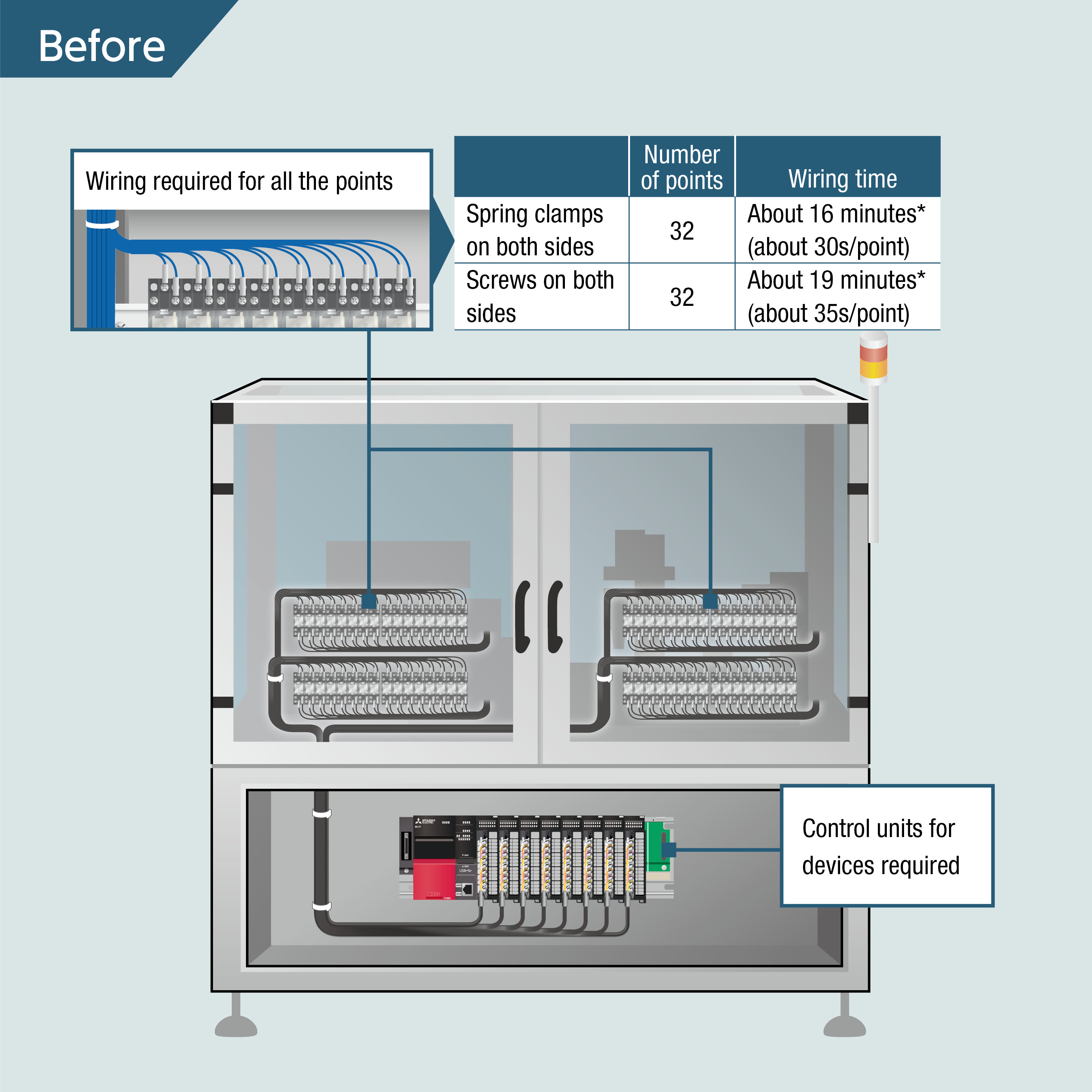
- Before
-
-
- After-1
-
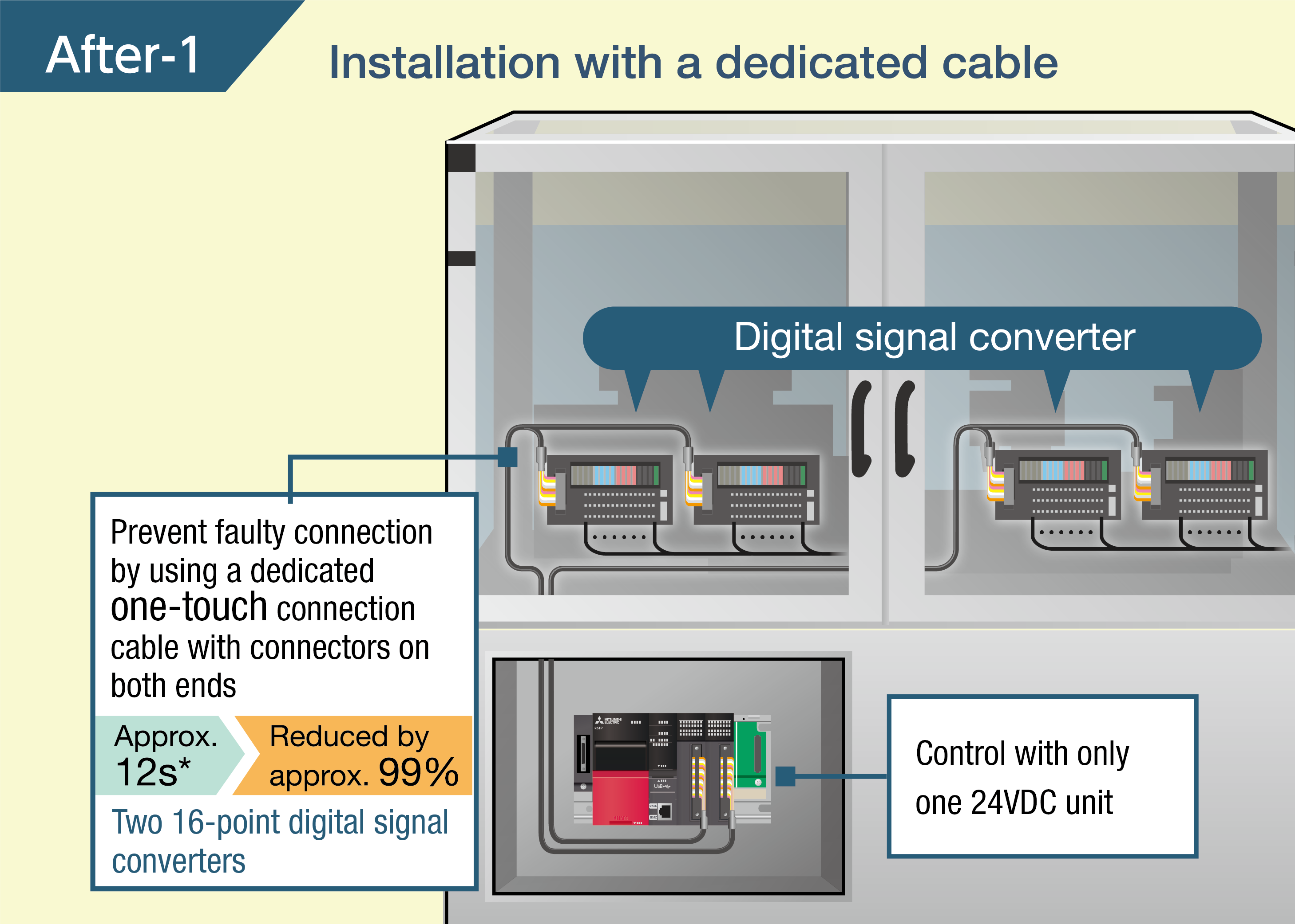
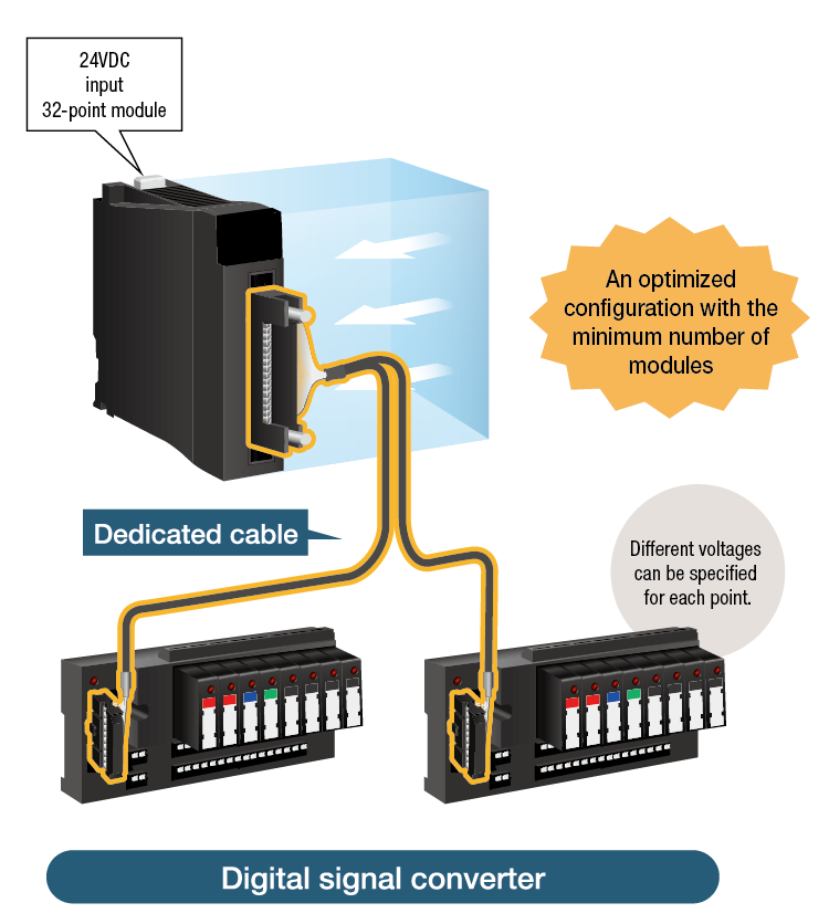
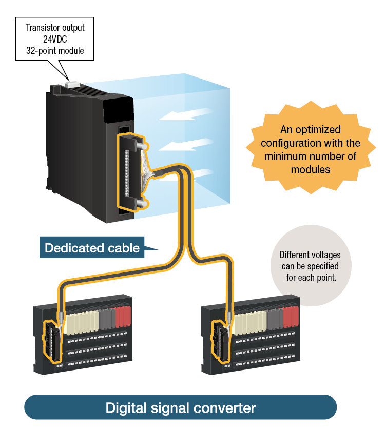
- Dedicated cable for "device optimization" and "wire saving"
- After-2
-
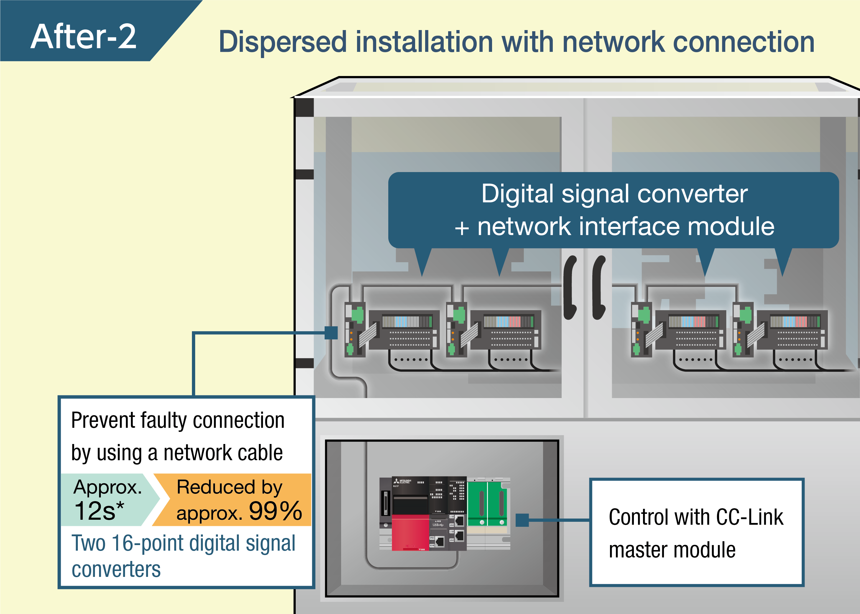
- Network interface module for "device optimization" and "wire saving"
Optimal installation , easy wiring , space saving
Since modules can be individually specified, systems can be configured with a minimum number of points. In addition, the number of connectable programmable controllers is optimized and wiring work can be reduced by using the dedicated cable.
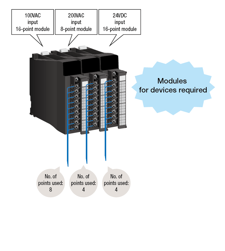
Input type
(Example) Configuration of the following three modules: 100-VAC input 8-point module, 200-VAC input 4-point module, and 24-VDC input 4-point module
-
- Before
-
- After
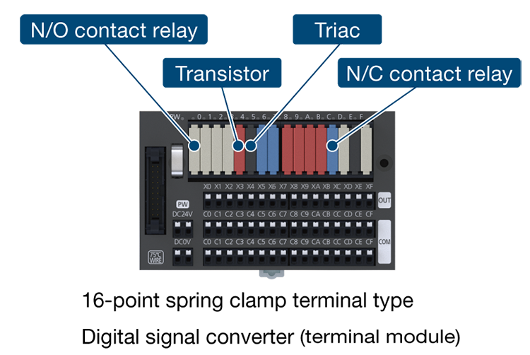
Output type
(Example) Configuration of the following three modules: relay output 16-point module, triac output 8-point module, and transistor output 8-point module.
-
- Before

-
- After
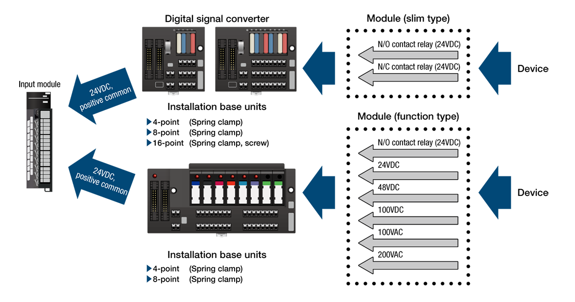
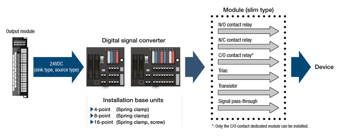
Converting signals into digital signals that can be handled by the connected device
By using a digital signal converter (terminal module), only 24VDC modules are required on the programmable controller side and signals output from the programmable controller can be converted into signals that can be handled by the connected device.
The number of spare products can be reduced as well.
Input type
Selectable connection method
-
- Direct wiring to a programmable controller
- • One-touch connection using a dedicated cable reduces cost and time for wiring.
• Using a dedicated cable prevents faulty connection.
- Direct wiring to a programmable controller
-
- Dispersed installation in the equipment on the industrial network
- • With network connection, "installation in the equipment: installation near devices" can be achieved instead of "installation in the control panel".
• Installing the product near devices improves the maintenance efficiency.
• Collecting sensor information wirelessly and monitoring the site remotely.
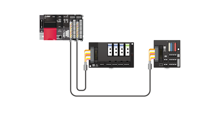
Distributed installation to meet the system needs
- Connection with the programmable controller using dedicated cable
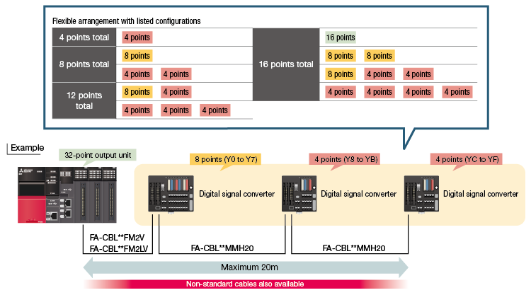
- Dedicated cables can be used to connect the input/output modules of the programmable controller system and the digital signal converters.
I/O numbers are automatically assigned according to the order in which digital signal converters are connected to the programmable controller.
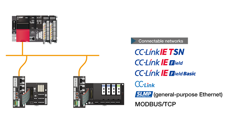
- Distributed installation using network connection cables
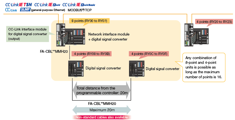
- Distributed installation of digital signal converters (terminal modules) connected over CC-Link IE TSN, CC-Link IE Field, CC-Link IE Field Basic, CC-Link, SLMP (standard Ethernet), or MODBUS/TCP is possible using network interface modules.
Selection of the control method per point
The control method can be selected and mixed per point using module type.
Easy maintenance
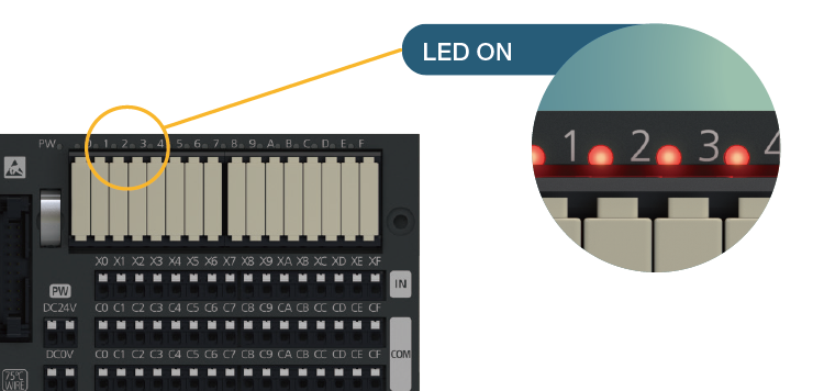
LED indication
The LED indication (red) helps identify whether input signals are on or off. Additionally, modules can be distinguished by marking strip color, model name, or module color.
-
- Slim module
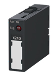
-
- Functional module
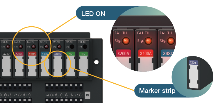
- Marking strip
• The module has a marking strip on the front.
• Input signals can be distinguished by the marking strip color and markings.
• Information can be written in the free space on the marking strip for easy management.
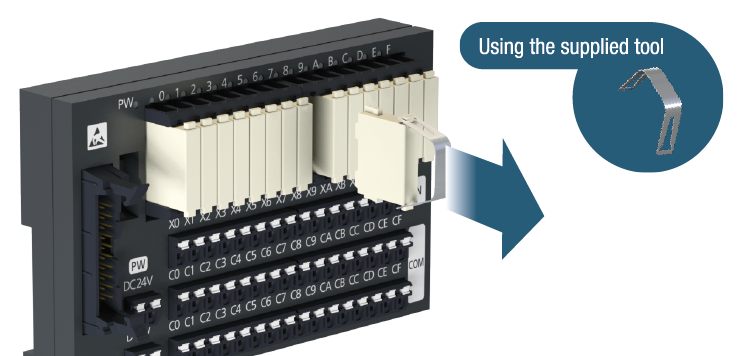
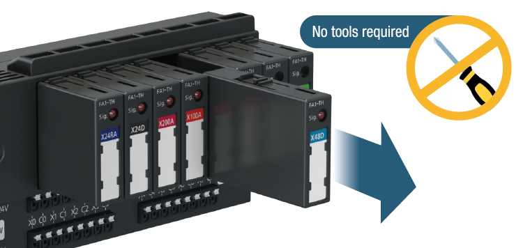
Module replacement
If a module fails or reaches the end of its service life, the module can be replaced using the supplied tool or without tools.
-
- Slim module
-
- Functional module
Continuity check using a tester port
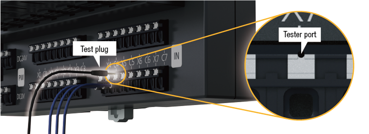
- The time required for continuity check can be reduced because the spring clamp terminal type product has a tester port.
Shared common
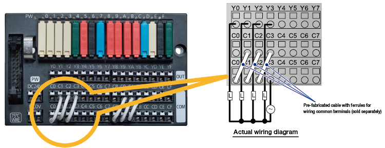
- Two sets of common terminals per input signal allows for common terminals to be shared.
[Example] Wiring when sharing the common terminals Y0 to Y3 in output digital signal converter.
Digital signal converters (terminal modules) - Selection utilizing module selectable type installation base unit
A digital signal converter (terminal module) enables devices with different voltage loads to be connected with the most suitable devices individually.
A spring clamp terminal block contributes to easy wiring, stable connection, and less maintenance.
